Students learning organic chemistry are often asked in examinations and tutorials to devise the mechanisms (as represented by curly arrows) for the core corpus of important reactions, with the purpose of learning skills that allow them to go on to improvise mechanisms for new reactions. A common question asked by students is how should such mechanisms be presented in an exam in order to gain full credit? Alternatively, is there a single correct mechanism for any given reaction? To which the lecturer or tutor will often respond that any reasonable mechanism will receive such credit. The implication is that a mechanism is “reasonable” if it “follows the rules”. The rules are rarely declared fully, but seem to be part of the absorbed but often mysterious skill acquired in learning the subject. These rules also include those governing how the curly arrows should be drawn.† Here I explore this topic using the Graham reaction.[1]‡
I start by noting the year in which the Graham procedure was published, 1965. Although the routine representation of mechanism using curly arrows had been established for about 5-10 years by then, the quality of such representations in many articles was patchy. Thus, this one (the publisher will need payment for me to reproduce the diagram here, so I leave you to get it yourself) needs some modern tidying up. In the scheme below, I have also made a small change, using water itself as a base to remove a NH proton, rather than hydroxide anion as used in the article (I will return to the anion later). The immediate reason is that water is a much simpler molecule to use at the start of our investigation than solvated sodium hydroxide. You might want to start with comparing the mechanism above with the literature version[1] to discover any differences.
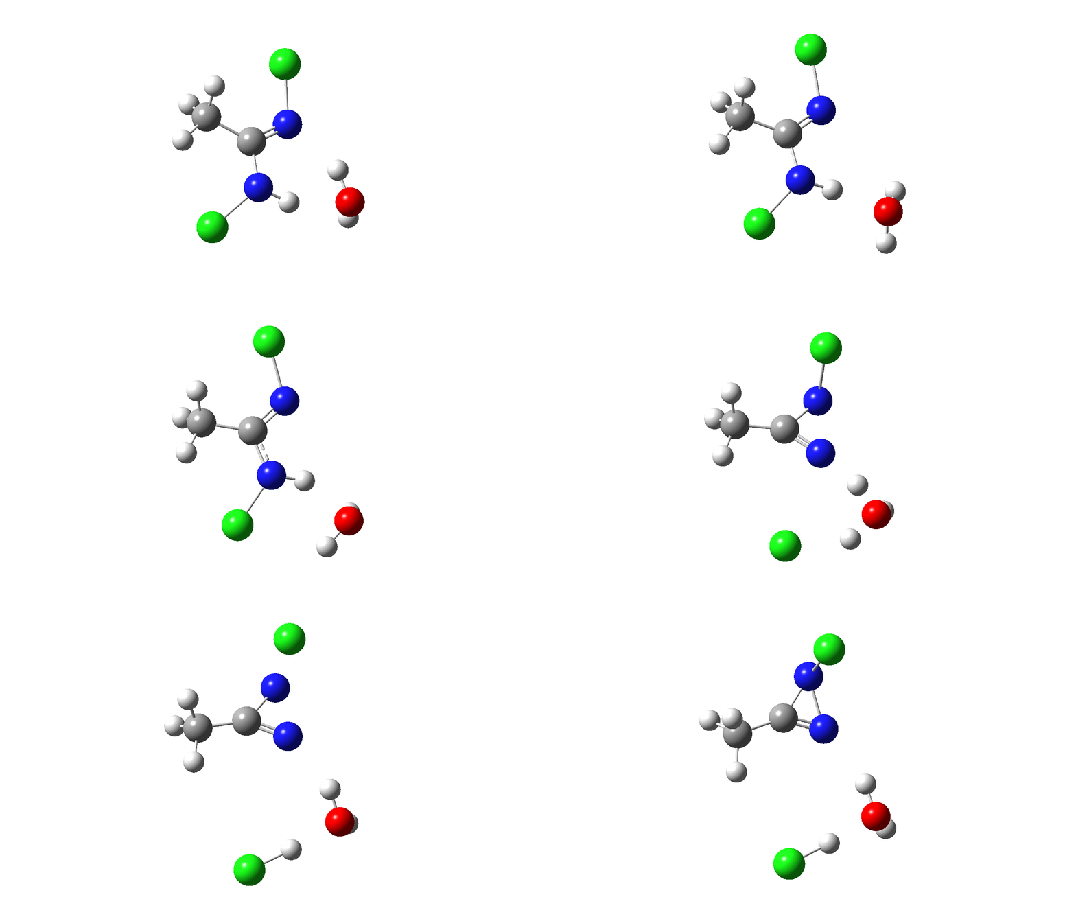
The next stage is to compute all of this using quantum mechanics, which will tell us about the energy of the system as it evolves and also identify the free energy of the transition states for the reaction. I am not going to go into any detail of how these energies are obtained, suffice to say that all the calculations can be found at the following DOI: 10.14469/hpc/5045 The results of this exercise are represented by the following alternative mechanism.♥
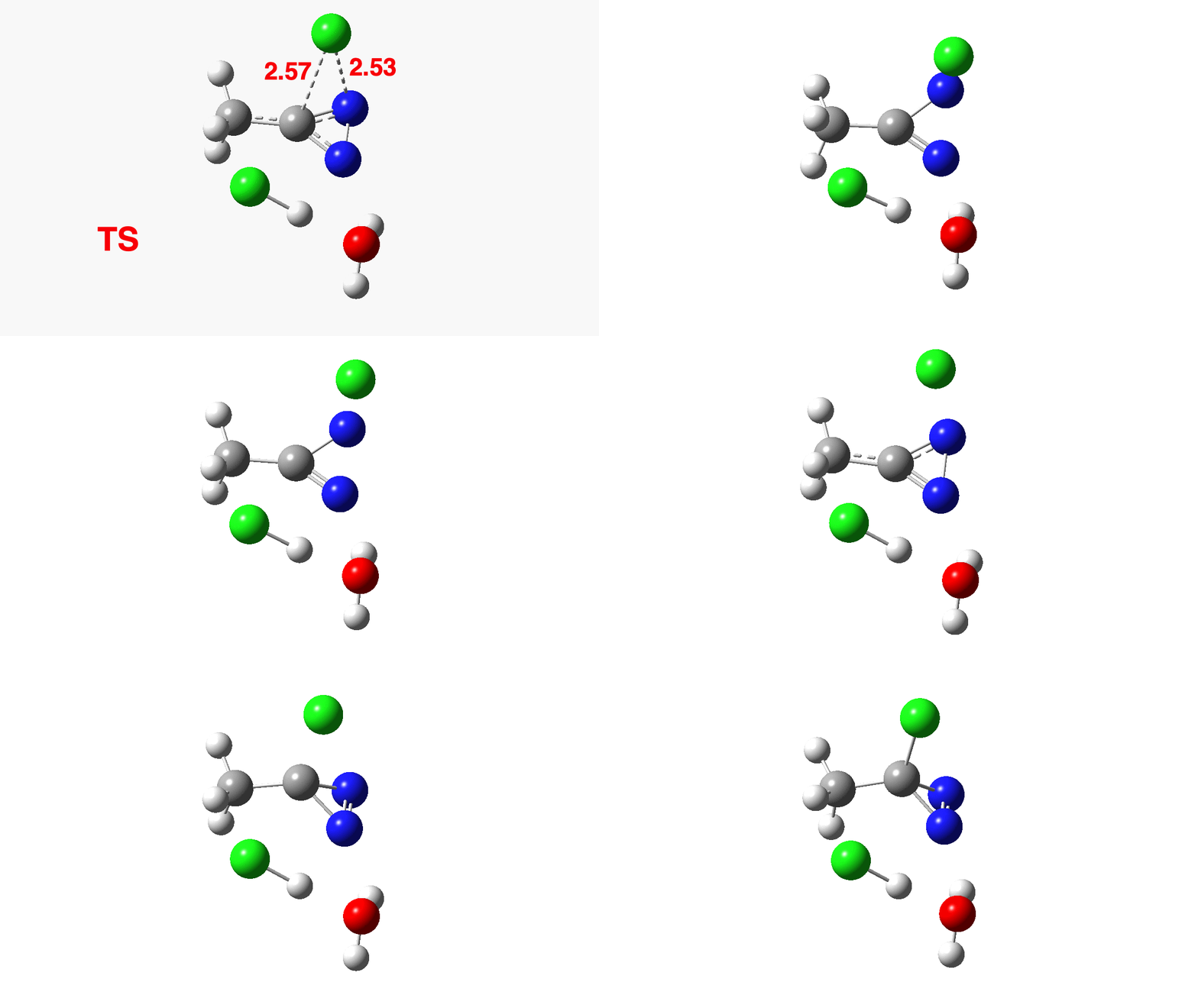
How was this new scheme obtained? The key step is locating a transition state in the energy surface, a point where the first derivatives of the energy with respect to all the 3N-6 coordinates defining the geometry (the derivative vector) are zero and where the second derivative matrix has just one negative eigenvalue (check up on your Maths for what these terms mean). Each located transition state (which is an energy maximum in just one of the 3N-6 coordinates) can be followed downhill in energy to two energy minima, one of which is declared the reactant of the reaction and the other the product, using a process known as an IRC (intrinsic reaction coordinate). The coordinates of these minima are then inspected so they can be mapped to the conventional representations shown above. New bonds in the formalism above are shown with dashed lines and have an arrow-head ending at their mid-point; breaking bonds (more generally, bonds reducing their bond order) have an arrow starting from their mid-point. The change in geometry along the IRC for TS1 can then be shown as an animation of the reaction coordinate, which you can see below.

Don’t worry too much about when bonds appear to connect or disconnect, the animation program simply uses a simple bond length rule to do this. The major difference with the original mechanism is that it is the chlorine on the nitrogen also bearing a proton that gets removed. Also, the N-N bond is formed as part of the same concerted process, rather than as a separate step.
Shown above is the computed energy along the reaction path. Here a “reality check” can be carried out. The activation free energy (the difference between the transition state and the reactant) emerges as a rather unsavoury ΔG‡=40.8 kcal/mol. Why is this unsavoury? Well, according to transition state theory, the rate of a (unimolecular) reaction is given by the expression: Ln(k/T) = 23.76 – ΔG‡/RT where T is temperature (~323K in this example), R = is the gas constant and k is the unimolecular rate constant. When you solve it for ΔG‡=40.8, it turns out to be a very slow reaction indeed. More typically, a reaction that occurs in a few minutes at this sort of temperature has ΔG‡= ~15 kcal/mol. So this turns out to be an “unreasonable” mechanism, but based on the quantum mechanically predicted rate and not on the nature of the “curly arrows”. And no, one cannot do this sort of thing in an examination (not even on a mobile phone; there is no app for it, yet!) I must also mention that the “curly arrows” used in the above representation are, like the bonds, based on simple rules of connecting a breaking with a forming bond with such an arrow. There IS a method of computing both their number and their coordinates “realistically”, but I will defer this to a future post. So be patient!
The next thing to note is that the energy plot shows this stage of the reaction as being endothermic. Time to locate TS2, which it turns out corresponds to the N to C migration of the chlorine to complete the Graham reaction. As it happens, TS2 is computed to be 10.6 kcal/mol lower than TS1 in free energy, so it is not “rate limiting”.

To provide insight into the properties of this reaction path, a plot of the calculated dipole moment along the reaction path is shown. At the transition state (IRC value = 0), the dipole moment is a maximum, which suggests it is trying to form an ion-pair, part of which is the diazacylopropenium cation shown in the first scheme above. The ion-pair is however not fully formed, probably because it is not solvated properly.
We can add the two reaction paths together to get the overall reaction energy, which is no longer endothermic but approximately thermoneutral. Things are still not quite “reasonable” because the actual reaction is exothermic.
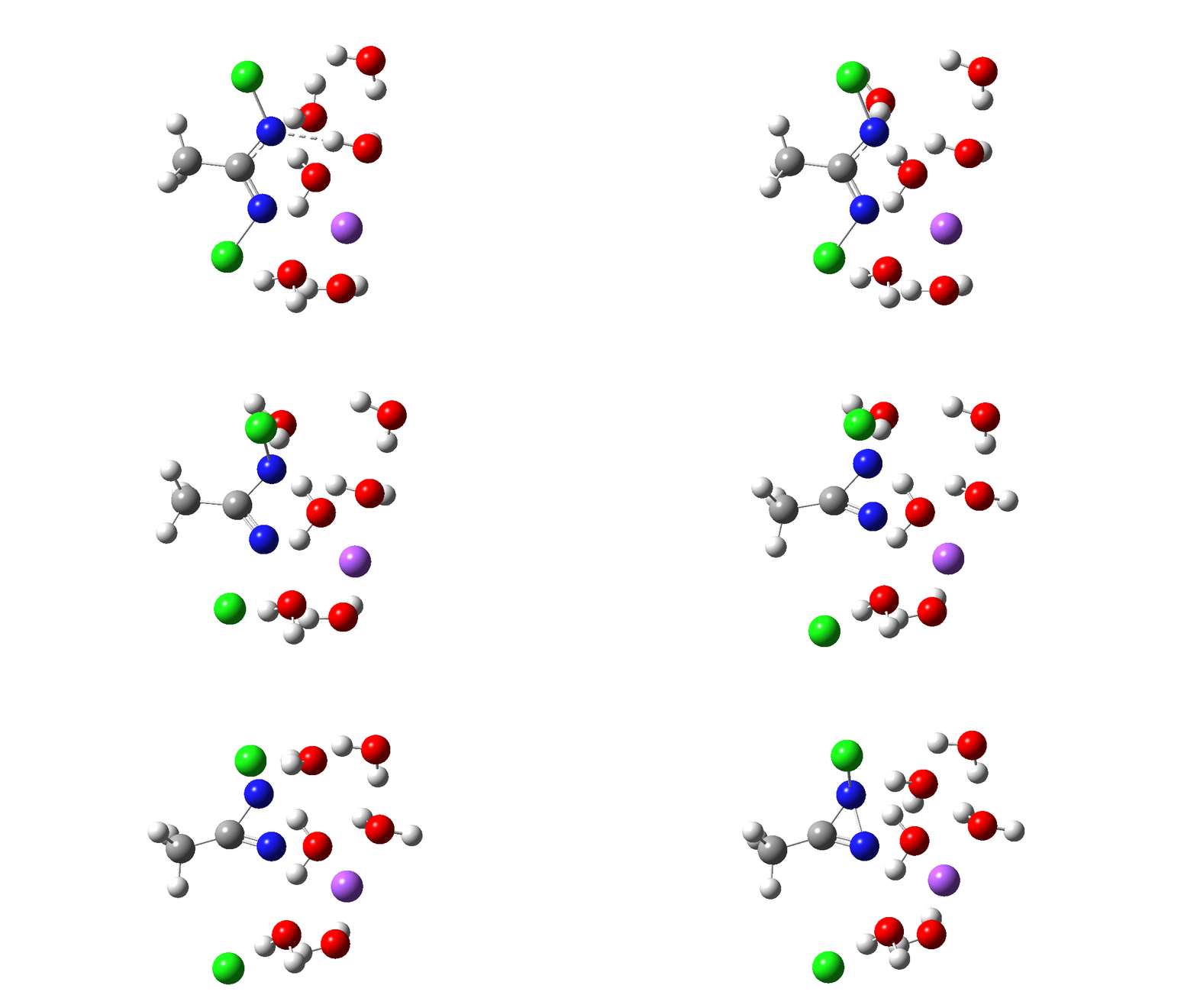
Time then to move on to hydroxide anion as the catalytic base, in the form of sodium hydroxide. To do this, we need to include lots of water molecules (here six), primarily to solvate the Na+ (shown in purple below) but also any liberated Cl–. You can see the water molecules moving around a lot as the reaction proceeds, via again TS1 to end at a similar point as before.

The energy plot is now rather different. The activation energy is now lower than the 15 kcal/mol requirement for a fast reaction; in fact ΔG‡= 9.5 kcal/mol and overall it is already showing exothermicity. What a difference replacing a proton (from water) by a sodium cation makes!
Take a look also at this dipole moment plot as the reaction proceeds! TS1 is almost entirely non-ionic!
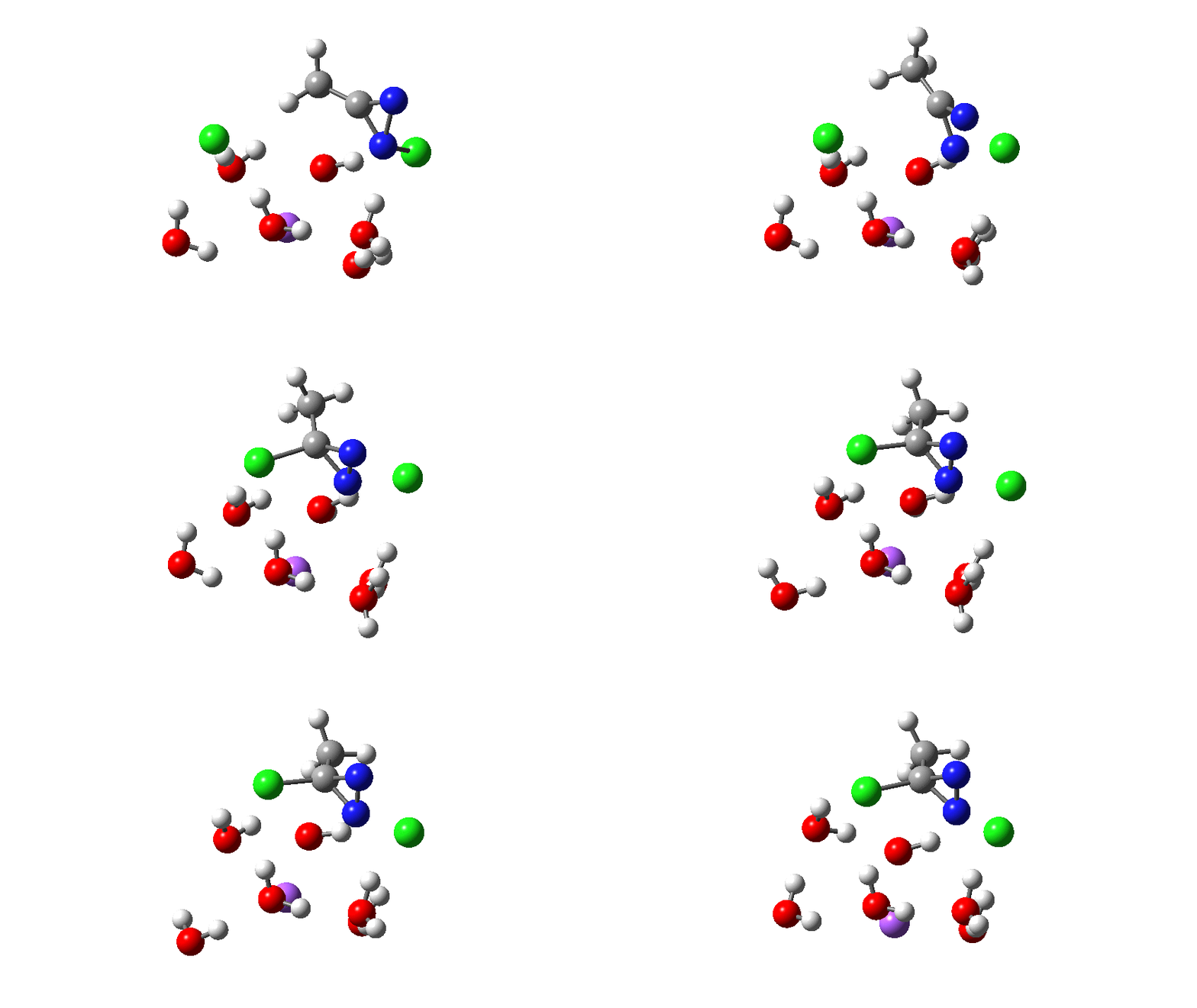
To complete the reaction, the chlorines have to rearrange. This time a rather different mode is adopted, as shown below, termed an Sn2′ reaction. The energy of TS2′ is again lower than TS1, by 9.2 kcal/mol. Again no explicit diazacylopropenium cation-anion pair (an aromatic 4n+2, n=0 Hückel system) is formed.
Combing both stages of the reaction as before. The discontinuity in the centre is due to further solvent reorganisation not picked up at the ends of the two individual IRCs which were joined to make this plot. Note also that the reaction is now appropriately exothermic overall.
So what have we learnt?
- That a “reasonable” mechanism as shown in a journal article, and perhaps reproduced in a text-book, lecture or tutorial notes or even an examination, can be subjected in a non-arbitrary manner to a reality check using modern quantum mechanical calculations.
- For the Graham reaction, this results in a somewhat different pathway for the reaction compared to the original suggestion.
- In particular, the removal of chlorine occurs from the same nitrogen as the initial deprotonation
- This process does not result in an intermediate nitrene being formed, rather the chlorine removal is concerted with N-N bond formation.
- The resulting 1-chloro-1H-diazirine does not directly ionize to form a diazacyclopropenium cation-chloride anion ion pair, but instead can undertake an Sn2′ reaction to form the final 3-chloro-3-methyl-3H-diazirine.
- A simple change in the conditions, such as replacing water as a catalytic agent with Na+OH–(5H2O) can have a large impact on the energetics and indeed pathways involved. In this case, the reaction is conducted in NaOCl or NaOBr solutions, for which the pH is ~13.5,♣ indicating [OH–] is ~0.3M.
- The curly arrows here are “reasonable” for the computed pathway, but are determined by some simple formalisms which I have adopted (such as terminating an arrow-head at the mid-point of a newly forming bond). As I hinted above, these curly arrows can also be subjected to quantum mechanical scrutiny and I hope to illustrate this process in a future post.
But do not think I am suggesting here that this is the “correct” mechanism, it is merely one mechanism for which the relative energies of the various postulated species involved have been calculated relatively accurately. It does not preclude that other, perhaps different, routes could be identified in the future where the energetics of the process are even lower.
†This blog is inspired by the two students who recently asked such questions. ‡In fact, you also have to acquire this completely unrelated article[2] for reasons I leave you to discover yourself. ♥You might want to consider the merits or demerits of an alternative way of showing the curly arrows. Is this representation “more reasonable”? ♣I thank Ed Smith for measuring this value for NaOBr and for suggesting the Graham reaction in the first place as an interesting one to model.
References
- W.H. Graham, "The Halogenation of Amidines. I. Synthesis of 3-Halo- and Other Negatively Substituted Diazirines<sup>1</sup>", Journal of the American Chemical Society, vol. 87, pp. 4396-4397, 1965. https://doi.org/10.1021/ja00947a040
- E.W. Abel, B.C. Crosse, and D.B. Brady, "Trimeric Alkylthiotricarbonyls of Manganese and Rhenium", Journal of the American Chemical Society, vol. 87, pp. 4397-4398, 1965. https://doi.org/10.1021/ja00947a041
Tags: /RT, activation energy, activation free energy, animation, arrow pushing, arrow-head, cellular telephone, Chemical kinetics, chemical reaction, Chemistry, computed energy, Ed Smith, energy, energy maximum, energy minima, energy plot, energy profile, energy surface, free energy, lecturer, mechanism, Natural sciences, Organic chemistry, overall reaction energy, Physical sciences, Reaction rate constant, Resonance, Transition state, Transition state theory, tutor, Tutorial
